No products in the cart.

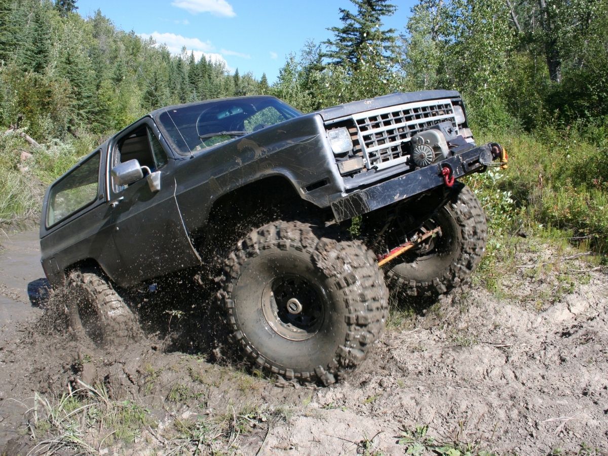
More Australians are turning their diesel and petrol 4WDs into electric vehicles through conversion programs. It is a way to keep much loved LandCruisers, Patrols, Hiluxes and similar models on the road while removing the fuel tank and installing an electric drivetrain. What surprises many owners is that these conversions often keep large parts of the existing driveline in place.
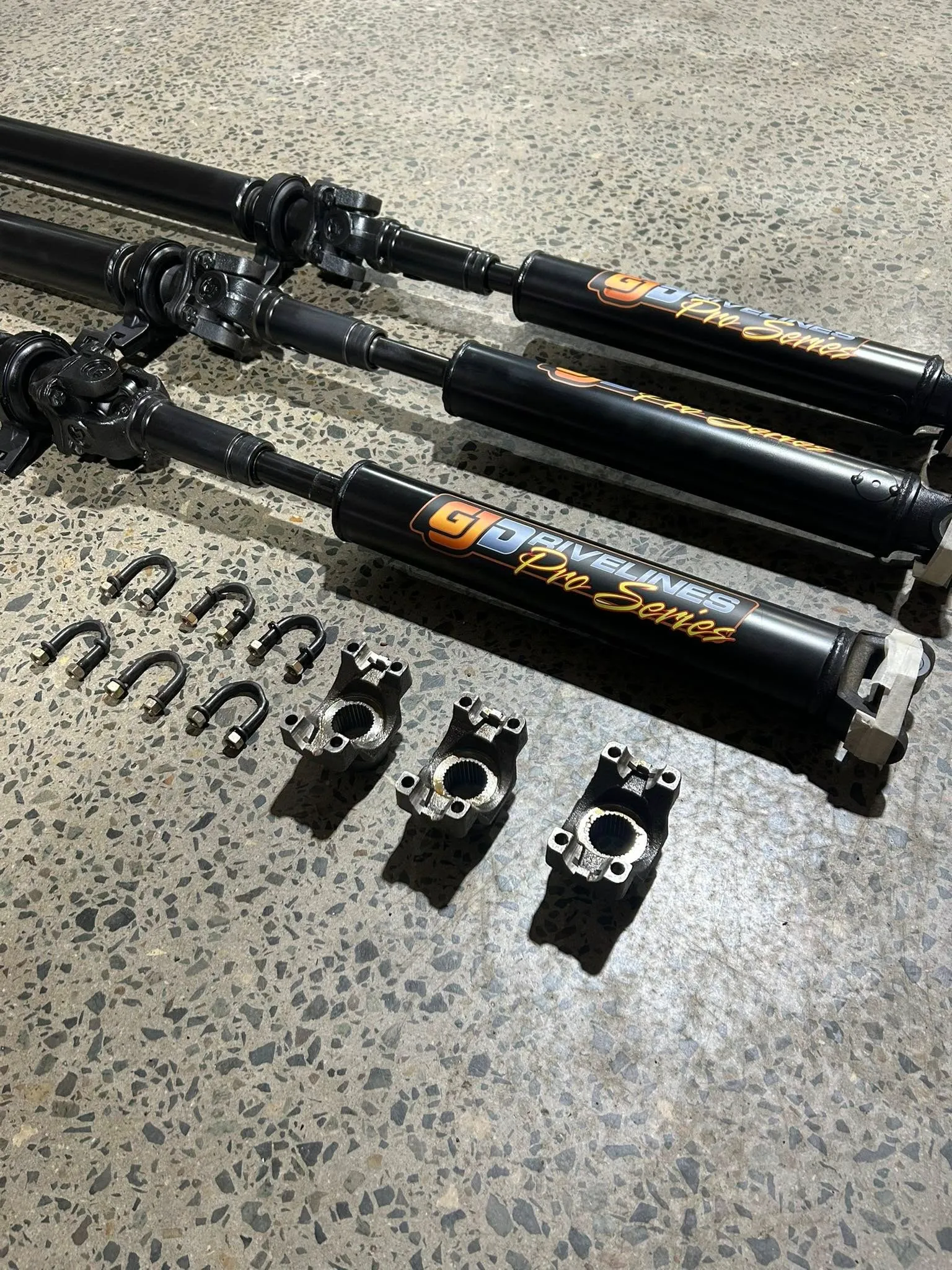
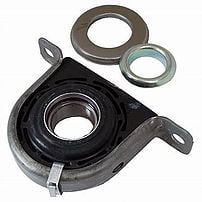
Unlike new electric utes that are designed from the ground up without a tailshaft, conversions usually retain the original driveline. The gearbox, tailshaft, centre bearing and differentials are left to do their job, only now they must manage torque that arrives instantly from an electric motor. That change in stress patterns is where driveline specialists come in.
One of the biggest challenges is vibration. A tailshaft that was acceptable behind a diesel may show imbalance once paired with an EV motor. This is because the motor delivers peak torque at low speed, so any imbalance is felt more sharply by the driver. Precision balancing is often required, and in some cases, upgraded centre bearings or heavy duty universal joints are installed to cope with the load.
BITRE’s Road Vehicles Australia (January 2024) gives data on the number of registered BEVs and FCEVs, showing EV ownership is increasing sharply.
https://www.bitre.gov.au/publications/2024/road-vehicles-australia-january-2024
Current statistics on the number of EV vehicles by brand.
https://thedriven.io/2025/09/03/australian-electric-vehicle-sales-by-month-and-by-model-in-2025-2
Retaining the differential keeps gearing and 4WD capability intact. It also avoids expensive custom solutions. During conversions, differentials are typically inspected, resealed, or rebuilt to ensure reliability under new torque conditions.
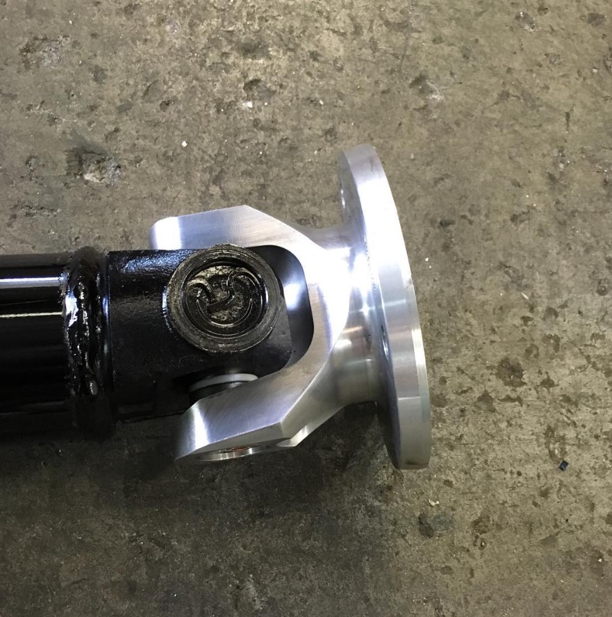
Workshops in Sydney and Melbourne note that driveline vibration and wear are among the most common challenges after an EV motor is installed. Often this is because the tailshaft or bearings were already worn before conversion, and the added torque makes issues surface sooner.


Chrysler – Dodge
727 – 30 Spline 1 11/16″ Seal Diameter
904 – 26 Spline 1 9/16″ Seal Diameter
Ford
C6-T56 – 31 Spline 1 11/16″ Seal Diameter
AOD & C4 & T5 – 28 Spline 1 1/2″ Seal Diameter
4 R 7OW – 28 Spline 1.598″ Seal Diameter
General Motors
T-350 700R4-4LLOE – 27 Spline 1 1/2″ Seal Diameter
T-400-4L80E – 32 Spline 1 7/8″ Seal Diameter
Note: Transmission slip yokes are manufactured with various U-Joint Series. It is important to match Horsepower and Torque requirements to U-Joint Series. For aftermarket transmission applications usually a spline count and seal diameter will identify slip yoke required.

If Pinion Yoke has Placement tabs that retain the U-Joint, measure inside tabs. See Diagram D.

If Pinion Yoke does not have Placement Tabs that retain U-Joint, measure from flat of yoke inside to inside. See Diagram E.

If 4 bolt Flange is used on pinion, measure Pilot Diameter and center to center diagonally bolt hole to bolt hole. See Diagram L.

Universal Joint Size. There are hundreds of U-Joint sizes or “Series” to accomodate many different applications of power and desired longevity for your automotive, 4×4 truck or auto racing requirements, these 4 series of joints cover most needs.
1310 Spicer Series: 1 1/16″ Cup Diameter (Dim C – Diagram A) 3 7/32″ length (Dim B – Diagram A) Certain Ford applications have 2 cups 1 1/8 Diameter. Appropriate horse power range is up to 500 in circle track or road racing, small tire drag racing and 4×4. Also available: Performance Dynamic Cryo Joint.
1330 Spicer Series: 1 1/16″ Cup Diameter (Dim C – Diagram A) 3 5/8″ length (Dim B – Diagram A) Certain Ford applications have 2 cups 1 1/8 Diameter. Slightly stronger than 1310, Used in 5.0 Mustangs. Also available: Performance Dynamic Cryo Joint.
3R Saginaw Series: 1 1/8″ Cup Diameter (Dim C – Diagram A) Retained with internal clip 2 5/8″ (Dim B – Diagram A). Most common GM joint. Horse power range up to 700 in road racing and circle track. Solid drag racing U-Joint can accomodate most sportsman classes. Also available: Performance Dynamic Cryo Joint.
1350 Spicer Series: Manufactured with OEM tolerances and treated with our Cryogenic Process to yeild the strongest U-Joint available. For drag racing applications a solid non-lube design U-Joint is recommended because of the tremendous initial shock load, or short duration of high torque the joint must be able to withstand.

If PST is supplying you with transmission slip yoke, Pinion yoke and driveshaft yoke measure Dim W. See Diagram N.
If PST is supplying you with transmission slip yoke and driveshaft measure Dim X. See Diagram N.
2 Piece driveshafts use Dim Y + Z. See Diagram N.