No products in the cart.

All Categories
All Categories
external
variable
grouped
simple
[fibosearch]
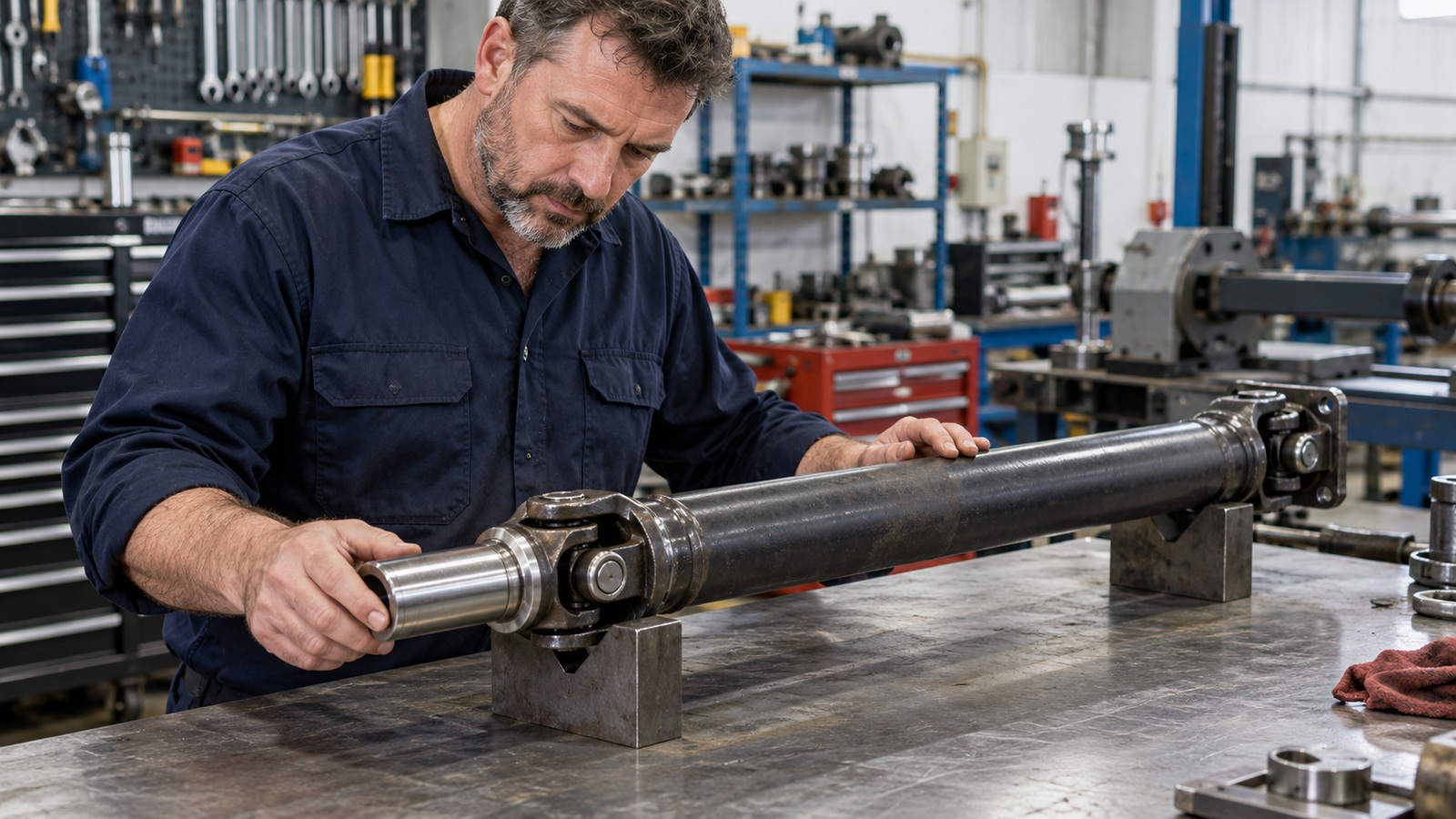
A driveshaft slip yoke gives a shaft assembly room to change its working length. Where suspension movement changes the distance between the driveline’s connection points, the sliding connection takes up that change. The shaft tube does not have to stretch. The sliding connection’s position depends on the driveline design.
That designed sliding travel is different from excessive sideways looseness. The distinction helps explain the component’s job. It does not tell you whether a particular shaft is worn or which replacement will fit.
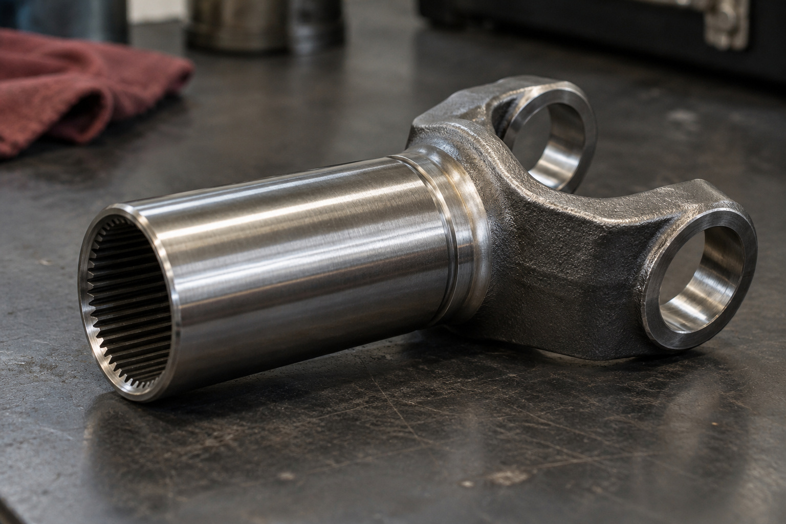
The Spicer 10 Series Driveshaft Service Manual defines a slip yoke as a fitting that accommodates axial movement. Axial means along the length of the shaft. Its glossary calls the total permitted travel slip.
In a splined sliding connection, matching teeth allow the members to slide while passing on turning force. The working length changes at the connection, rather than through the tube stretching. The parts still need to match the design they belong to.
Driveshaft manufacturer Neapco describes traditional slip-yoke arrangements and a different sliding design within the shaft. Its slip-in-tube design uses matching splines to transmit turning force while allowing suspension travel. That is an example of the same need being handled in different ways, not proof that every vehicle uses a slip yoke at the gearbox.
The travel available is part of the particular assembly’s design. The word slip does not supply a standard distance for every shaft. The relevant specifications need to cover the assembly and its application, not just a component with a familiar name.
Diagrams of shaft ends and dimensions show where fittings sit. They are useful reference material, but a drawing alone cannot establish the correct part for your vehicle.
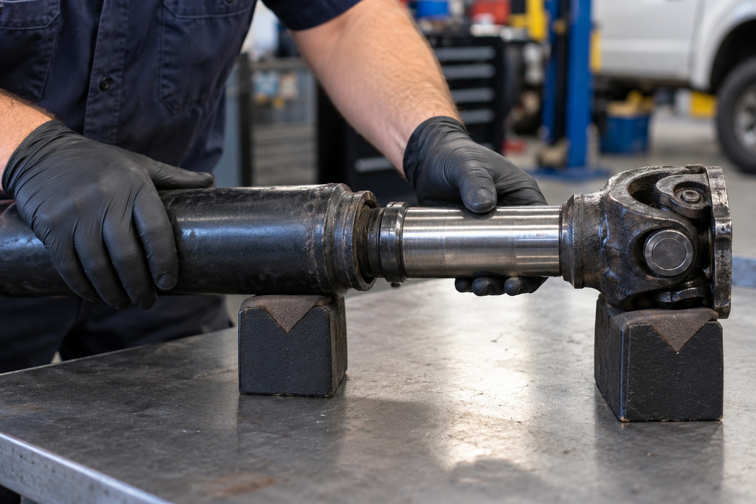
The direction of movement matters:
Spicer warns that excessive radial looseness in its slip-member assembly can cause imbalance or vibration. That can lead to component wear and driveline separation. The warning concerns its own components; it is not a diagnosis for every shaft.
The warning passage does not give a universal limit for sideways movement. What is excessive needs to be assessed against the relevant assembly and its specifications. Movement you can feel, or the absence of it, cannot settle that question by itself.
Spicer’s safety section says not to attempt driveline service or maintenance without the required training, tools and equipment.
Understanding the sliding function is useful when discussing a part. Choosing one still means matching it to the complete driveline. Similar-looking fittings are not proven interchangeable by their appearance or name.
The application discussion needs to cover:
These are connected details. A fitting has to work with the parts around it, not merely resemble the one in a photograph. Spicer’s glossary distinguishes slip yokes, yoke shafts and tube yokes, which is another reason to identify the assembly rather than rely on one label.
GJ’s published forms ask for gearbox, differential and rear universal-joint information, as well as applicable shaft dimensions. That supports a discussion about the complete application. It does not turn the reference tables into a universal interchange rule or prove that a named component is in stock.
The separate guide to ordering a custom tailshaft from interstate explains that ordering process. Use it for the required information rather than guessing dimensions from a general explanation of slip-yoke movement.
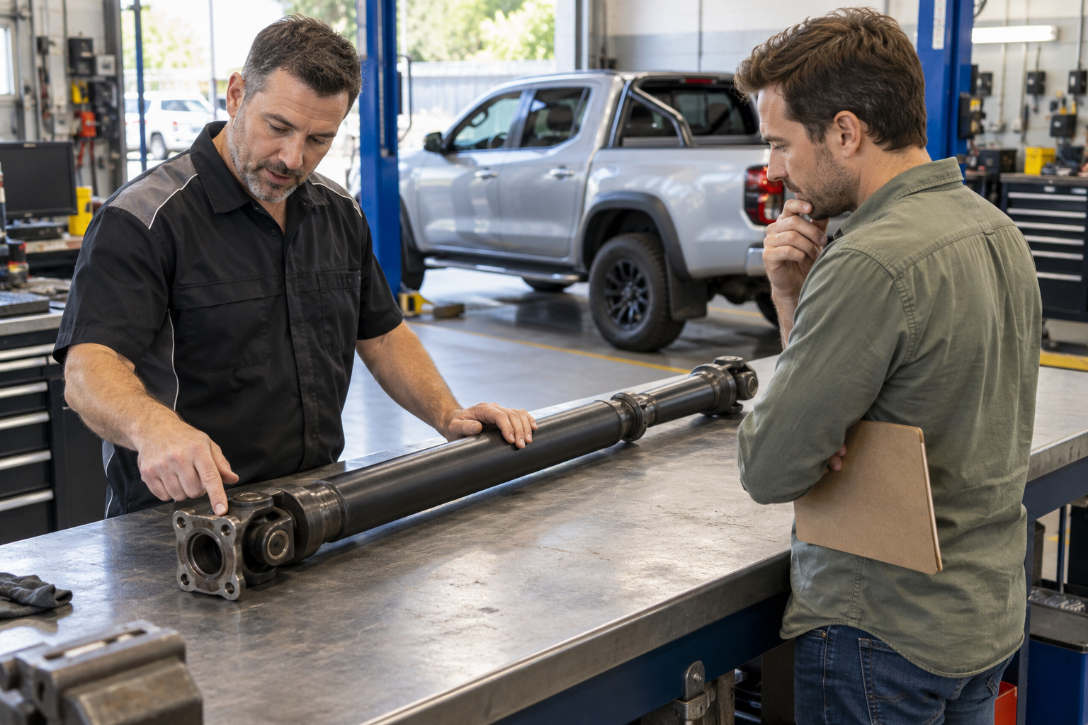
GJ Drivelines publishes custom tailshaft manufacturing, repairs, balancing and replacement-component services. When you get a quote, provide the vehicle make and model, engine, gearbox and differential details. Explain the application and include confirmed shaft information you already have.
The quote route has its own forms for the details needed. If something is unknown, say so rather than treating a component name as a complete specification. A qualified assessment and the relevant manufacturer’s information still govern the part choice.


Chrysler – Dodge
727 – 30 Spline 1 11/16″ Seal Diameter
904 – 26 Spline 1 9/16″ Seal Diameter
Ford
C6-T56 – 31 Spline 1 11/16″ Seal Diameter
AOD & C4 & T5 – 28 Spline 1 1/2″ Seal Diameter
4 R 7OW – 28 Spline 1.598″ Seal Diameter
General Motors
T-350 700R4-4LLOE – 27 Spline 1 1/2″ Seal Diameter
T-400-4L80E – 32 Spline 1 7/8″ Seal Diameter
Note: Transmission slip yokes are manufactured with various U-Joint Series. It is important to match Horsepower and Torque requirements to U-Joint Series. For aftermarket transmission applications usually a spline count and seal diameter will identify slip yoke required.

If Pinion Yoke has Placement tabs that retain the U-Joint, measure inside tabs. See Diagram D.

If Pinion Yoke does not have Placement Tabs that retain U-Joint, measure from flat of yoke inside to inside. See Diagram E.

If 4 bolt Flange is used on pinion, measure Pilot Diameter and center to center diagonally bolt hole to bolt hole. See Diagram L.

Universal Joint Size. There are hundreds of U-Joint sizes or “Series” to accomodate many different applications of power and desired longevity for your automotive, 4×4 truck or auto racing requirements, these 4 series of joints cover most needs.
1310 Spicer Series: 1 1/16″ Cup Diameter (Dim C – Diagram A) 3 7/32″ length (Dim B – Diagram A) Certain Ford applications have 2 cups 1 1/8 Diameter. Appropriate horse power range is up to 500 in circle track or road racing, small tire drag racing and 4×4. Also available: Performance Dynamic Cryo Joint.
1330 Spicer Series: 1 1/16″ Cup Diameter (Dim C – Diagram A) 3 5/8″ length (Dim B – Diagram A) Certain Ford applications have 2 cups 1 1/8 Diameter. Slightly stronger than 1310, Used in 5.0 Mustangs. Also available: Performance Dynamic Cryo Joint.
3R Saginaw Series: 1 1/8″ Cup Diameter (Dim C – Diagram A) Retained with internal clip 2 5/8″ (Dim B – Diagram A). Most common GM joint. Horse power range up to 700 in road racing and circle track. Solid drag racing U-Joint can accomodate most sportsman classes. Also available: Performance Dynamic Cryo Joint.
1350 Spicer Series: Manufactured with OEM tolerances and treated with our Cryogenic Process to yeild the strongest U-Joint available. For drag racing applications a solid non-lube design U-Joint is recommended because of the tremendous initial shock load, or short duration of high torque the joint must be able to withstand.

If PST is supplying you with transmission slip yoke, Pinion yoke and driveshaft yoke measure Dim W. See Diagram N.
If PST is supplying you with transmission slip yoke and driveshaft measure Dim X. See Diagram N.
2 Piece driveshafts use Dim Y + Z. See Diagram N.