No products in the cart.

So, you’ve got a handle on the basics of tailshafts. You know what they do and why they’re important. But what about the how? How do these seemingly simple components handle the immense power and forces involved in propelling your vehicle?
Let’s delve into the fascinating world of tailshaft dynamics and engineering, going beyond the basics to explore the intricate design and functionality of these crucial parts.
A tailshaft isn’t just a spinning rod; it’s a carefully engineered component designed to withstand a complex interplay of forces. Torque from the engine, rotational speed, and the potential for vibration all play a significant role in tailshaft dynamics.
Engineers consider these factors when designing tailshafts to ensure they can handle the stresses of everyday driving, as well as more demanding applications like off-roading or towing.
The materials used in tailshaft construction are critical to its performance and durability. Different grades of steel and even composite materials are employed, each with its own balance of strength, weight, and cost.
Engineers carefully select materials based on the specific application and the forces the tailshaft is expected to encounter. A heavy-duty truck tailshaft, for example, will require different materials than the tailshaft in a small passenger car.
Vibration is the enemy of a smooth ride and can lead to premature wear and tear on your vehicle’s components.
Tailshaft balancing is a crucial process that ensures the weight distribution is even, minimizing vibrations at high speeds. This involves adding small weights to the tailshaft at specific locations to counteract any imbalances.
Think of it like balancing your wheels – it makes a huge difference in the overall driving experience.
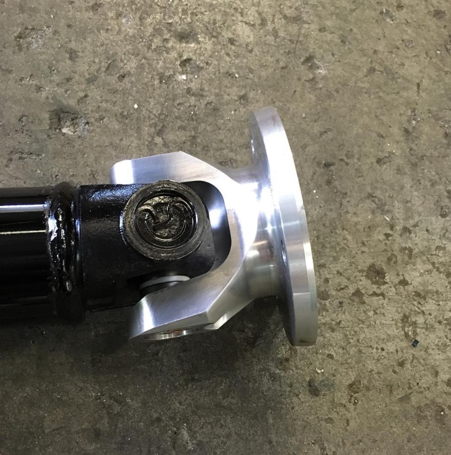
Universal joints, or U-joints, are essential components that allow the tailshaft to operate at different angles. They accommodate the movement of the suspension and the changes in angle between the gearbox and differential.
These joints are subject to significant stress and require regular lubrication and maintenance to prevent wear and tear. Their design is a marvel of engineering, allowing for flexibility without sacrificing strength.
Tailshaft length, diameter, and support systems are all carefully considered during the design process.
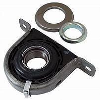
The length of the tailshaft affects its critical speed, which is the speed at which it begins to vibrate excessively. The diameter influences its strength and ability to transmit torque. And the support system, including the centre bearing, ensures stability and reduces the risk of vibration.
All these factors are intertwined and must be optimized for the specific vehicle application.
Ready to Dive Deeper?
Understanding the dynamics and engineering behind tailshafts can give you a greater appreciation for the complexity of your vehicle’s drivetrain.
If you’re interested in learning more about tailshafts or require expert advice, the team at GJ Drivelines is here to help.
Contact us today – we’re passionate about all things driveline!
So, you’ve got a handle on the basics of tailshafts. You know what they do and why they’re important. But what about the how? How do these seemingly simple components handle the immense power and forces involved in propelling your vehicle?
Let’s delve into the fascinating world of tailshaft dynamics and engineering, going beyond the basics to explore the intricate design and functionality of these crucial parts.
A tailshaft isn’t just a spinning rod; it’s a carefully engineered component designed to withstand a complex interplay of forces. Torque from the engine, rotational speed, and the potential for vibration all play a significant role in tailshaft dynamics.
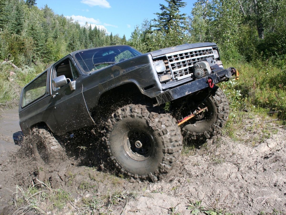
Engineers consider these factors when designing tailshafts to ensure they can handle the stresses of everyday driving, as well as more demanding applications like off-roading or towing.
The materials used in tailshaft construction are critical to its performance and durability. Different grades of steel and even composite materials are employed, each with its own balance of strength, weight, and cost.
Engineers carefully select materials based on the specific application and the forces the tailshaft is expected to encounter. A heavy-duty truck tailshaft, for example, will require different materials than the tailshaft in a small passenger car.
Vibration is the enemy of a smooth ride and can lead to premature wear and tear on your vehicle’s components.
Tailshaft balancing is a crucial process that ensures the weight distribution is even, minimizing vibrations at high speeds. This involves adding small weights to the tailshaft at specific locations to counteract any imbalances.
Think of it like balancing your wheels – it makes a huge difference in the overall driving experience.
Universal joints, or U-joints, are essential components that allow the tailshaft to operate at different angles. They accommodate the movement of the suspension and the changes in angle between the gearbox and differential.
These joints are subject to significant stress and require regular lubrication and maintenance to prevent wear and tear. Their design is a marvel of engineering, allowing for flexibility without sacrificing strength.
Tailshaft length, diameter, and support systems are all carefully considered during the design process.
The length of the tailshaft affects its critical speed, which is the speed at which it begins to vibrate excessively. The diameter influences its strength and ability to transmit torque. And the support system, including the centre bearing, ensures stability and reduces the risk of vibration.
All these factors are intertwined and must be optimized for the specific vehicle application.
Ready to Dive Deeper?
Understanding the dynamics and engineering behind tailshafts can give you a greater appreciation for the complexity of your vehicle’s drivetrain.
If you’re interested in learning more about tailshafts or require expert advice, the team at GJ Drivelines is here to help.
Contact us today – we’re passionate about all things driveline!


Chrysler – Dodge
727 – 30 Spline 1 11/16″ Seal Diameter
904 – 26 Spline 1 9/16″ Seal Diameter
Ford
C6-T56 – 31 Spline 1 11/16″ Seal Diameter
AOD & C4 & T5 – 28 Spline 1 1/2″ Seal Diameter
4 R 7OW – 28 Spline 1.598″ Seal Diameter
General Motors
T-350 700R4-4LLOE – 27 Spline 1 1/2″ Seal Diameter
T-400-4L80E – 32 Spline 1 7/8″ Seal Diameter
Note: Transmission slip yokes are manufactured with various U-Joint Series. It is important to match Horsepower and Torque requirements to U-Joint Series. For aftermarket transmission applications usually a spline count and seal diameter will identify slip yoke required.

If Pinion Yoke has Placement tabs that retain the U-Joint, measure inside tabs. See Diagram D.

If Pinion Yoke does not have Placement Tabs that retain U-Joint, measure from flat of yoke inside to inside. See Diagram E.

If 4 bolt Flange is used on pinion, measure Pilot Diameter and center to center diagonally bolt hole to bolt hole. See Diagram L.

Universal Joint Size. There are hundreds of U-Joint sizes or “Series” to accomodate many different applications of power and desired longevity for your automotive, 4×4 truck or auto racing requirements, these 4 series of joints cover most needs.
1310 Spicer Series: 1 1/16″ Cup Diameter (Dim C – Diagram A) 3 7/32″ length (Dim B – Diagram A) Certain Ford applications have 2 cups 1 1/8 Diameter. Appropriate horse power range is up to 500 in circle track or road racing, small tire drag racing and 4×4. Also available: Performance Dynamic Cryo Joint.
1330 Spicer Series: 1 1/16″ Cup Diameter (Dim C – Diagram A) 3 5/8″ length (Dim B – Diagram A) Certain Ford applications have 2 cups 1 1/8 Diameter. Slightly stronger than 1310, Used in 5.0 Mustangs. Also available: Performance Dynamic Cryo Joint.
3R Saginaw Series: 1 1/8″ Cup Diameter (Dim C – Diagram A) Retained with internal clip 2 5/8″ (Dim B – Diagram A). Most common GM joint. Horse power range up to 700 in road racing and circle track. Solid drag racing U-Joint can accomodate most sportsman classes. Also available: Performance Dynamic Cryo Joint.
1350 Spicer Series: Manufactured with OEM tolerances and treated with our Cryogenic Process to yeild the strongest U-Joint available. For drag racing applications a solid non-lube design U-Joint is recommended because of the tremendous initial shock load, or short duration of high torque the joint must be able to withstand.

If PST is supplying you with transmission slip yoke, Pinion yoke and driveshaft yoke measure Dim W. See Diagram N.
If PST is supplying you with transmission slip yoke and driveshaft measure Dim X. See Diagram N.
2 Piece driveshafts use Dim Y + Z. See Diagram N.