No products in the cart.

All Categories
All Categories
external
variable
grouped
simple
[fibosearch]
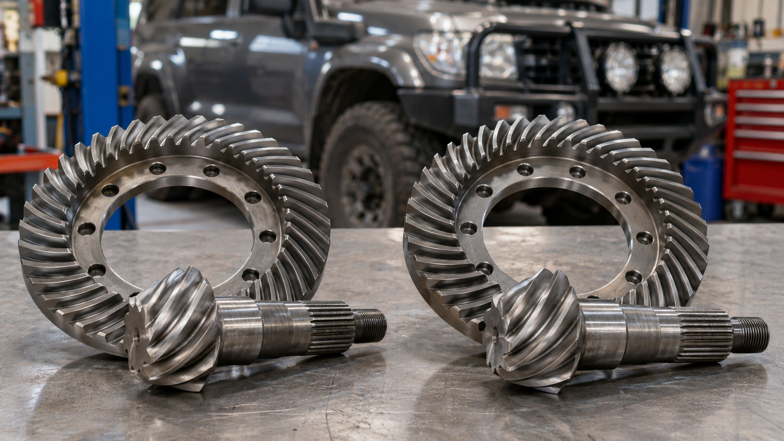
In a four-wheel drive that locks its front and rear tailshafts together, both diffs need the same gear ratio. The drivetrain is already forcing the front and rear wheels to turn at the same speed. Gear the two ends differently and they demand different wheel speeds from one locked drive, which the vehicle has no normal way to absorb.
The question usually comes up when one diff has to be replaced, or when a gear set is quoted for one end only.
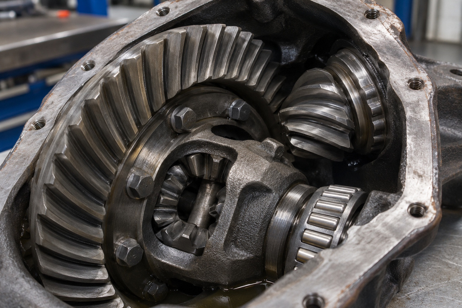
A diff ratio describes the gearing between two gears inside the diff housing. The pinion is the small gear the tailshaft drives. The ring gear, often called the crown wheel, is the large one it turns. Spicer, which makes ring and pinion sets, defines an axle ratio in exactly those terms. A 3.73 ratio means the pinion turns 3.73 times for every single turn of the ring gear.
The ratio ties the tailshaft to the ring gear and the carrier bolted to it. It does not fix the speed of either individual wheel. A diff exists so the two wheels on one axle can turn at different speeds through a corner, and they do.
Part-time four-wheel drive works by joining the front and rear tailshafts so they cannot turn independently. Ram’s owner’s manual for the 2022 2500 and 3500 covers the manually shifted transfer case. It says each four-wheel drive position, high range and low range, ‘locks the front and rear driveshafts together forcing the front and rear wheels to rotate at the same speed’. Not every four-wheel drive is built that way, so the first thing to establish is what sits under your own vehicle. The four-wheel drive section of your own handbook is where that is set out.
Now put two different ratios under a system like that. Each diff sets how fast that axle turns as a whole for a given tailshaft speed. Gear the front one way and the rear another, and the two axles call for different wheel speeds at the same moment. Meanwhile the transfer case is holding both tailshafts to one speed. The drivetrain is being asked to do two things at once, and nothing in it is designed to take up the difference.
The same manual shows how little slack a locked drive has. It warns that driving in those positions on dry, hard surfaced roads may cause increased tyre wear and damage to driveline components. That is on a vehicle whose front and rear gearing already match.
How that shows up, and how soon, depends on the vehicle, the surface and the driving. No general rule covers it.
These three get mixed up often, and they do different jobs.
| Part of the drivetrain | What it does | Can the driver select it? |
|---|---|---|
| Axle gear ratio | Sets how fast that axle turns for a given tailshaft speed | No. It is the gear set fitted inside the diff |
| Transfer case range | Changes the gearing between the gearbox and both tailshafts | Yes, with the range lever or switch |
| Differential lock | Stops the two wheels on one axle turning at different speeds | Only on a vehicle fitted with one |
Low range makes the point. The same Ram manual says engine speed in four-wheel drive low is about three times what it is in two-wheel drive high or four-wheel drive high at the same road speed. The whole vehicle is geared down, yet the gear sets inside the two diffs have not changed. Selecting a range never hands you a different pair of axle ratios.
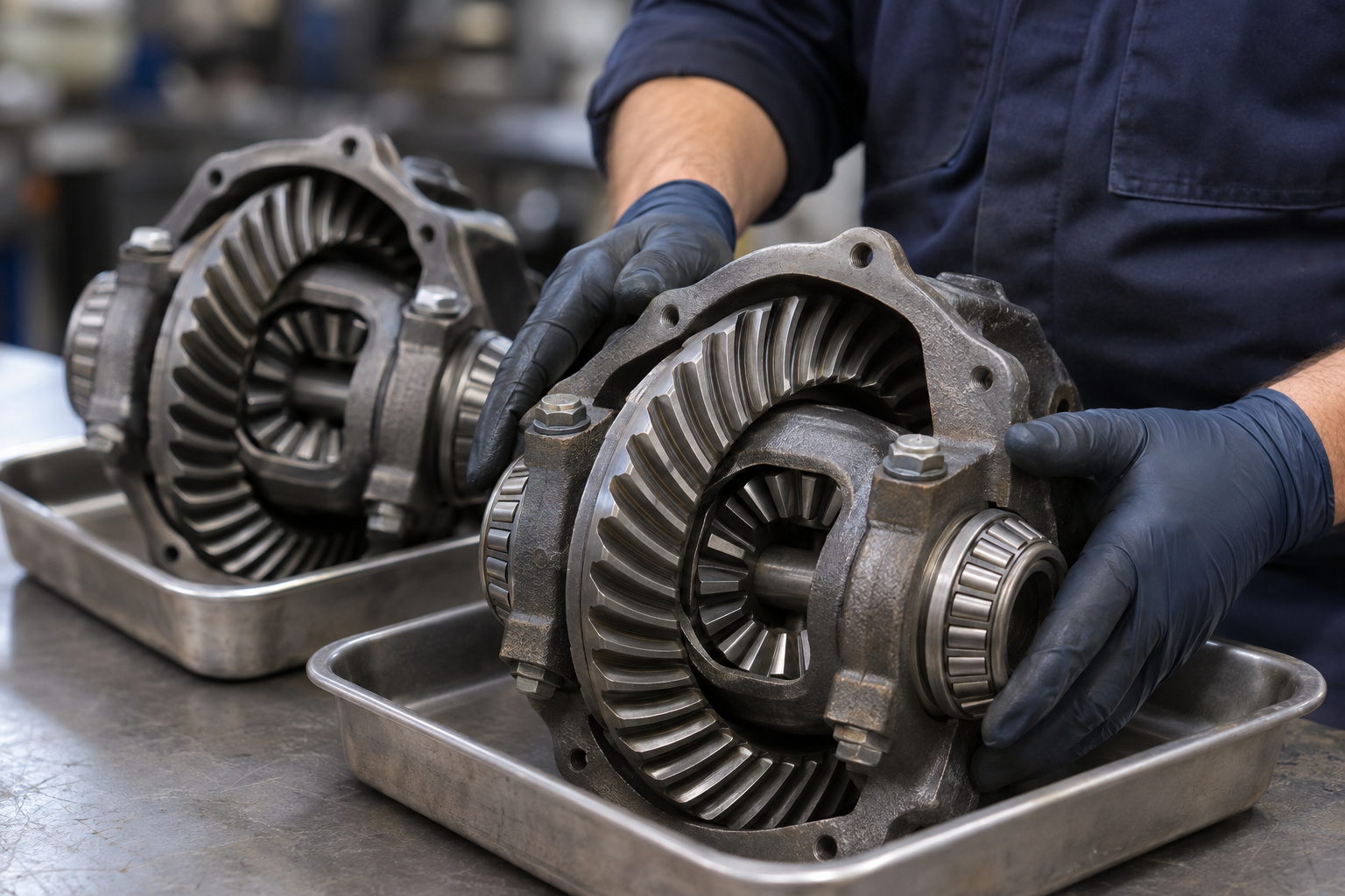
If a diff centre is replaced, or a new gear set goes into one axle, the other axle is part of the same decision. A housing that bolts straight up gives no promise about the gearing inside it.
A ratio printed on a box is a label, not a fitment check. Gear sets are listed for particular axles in particular vehicles, and the maker promises nothing beyond that listing. Spicer’s gear ratio page, published by Dana, states that Dana ‘makes no representation as to what equipment or use is appropriate for any specific vehicle’. The fitment answer comes from the vehicle’s own specification and the gear set’s listed application.
Rear-wheel-drive cars raise a separate question. Working out whether a Falcon or Commodore has an M78, M80 or M86 centre is its own job, and it sits outside front-to-rear matching.
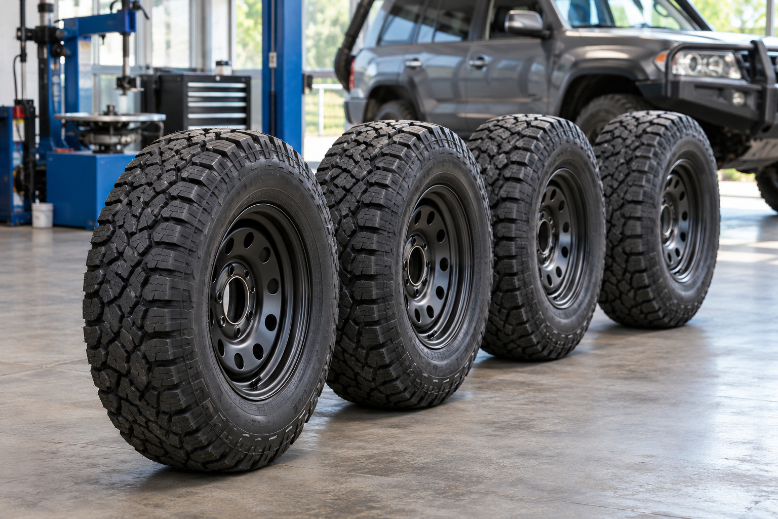
Matched gearing does not finish the job. The same Ram manual says proper operation of a four-wheel drive depends on tyres of equal size, type and circumference on each wheel.
The reason follows from everything above. A tyre with a different rolling circumference covers a different distance per turn. Two axles with identical gearing can still end up turning at different speeds because of it. Gearing and tyres are two separate requirements, and meeting one does not excuse the other.
What counts as acceptable is set by the vehicle manufacturer and published in the handbook for your own vehicle. No general percentage applies across vehicles.
Before any gear set is ordered, these are worth settling:
If the diffs are coming apart because of wear or noise rather than a ratio change, that is a different problem, and whether a 4×4 needs a differential rebuild before a summer trip covers it. That one is about condition and repair. When you want to talk through a driveline component for a particular vehicle before committing to anything, start with the driveline parts range at GJ Drivelines.


Chrysler – Dodge
727 – 30 Spline 1 11/16″ Seal Diameter
904 – 26 Spline 1 9/16″ Seal Diameter
Ford
C6-T56 – 31 Spline 1 11/16″ Seal Diameter
AOD & C4 & T5 – 28 Spline 1 1/2″ Seal Diameter
4 R 7OW – 28 Spline 1.598″ Seal Diameter
General Motors
T-350 700R4-4LLOE – 27 Spline 1 1/2″ Seal Diameter
T-400-4L80E – 32 Spline 1 7/8″ Seal Diameter
Note: Transmission slip yokes are manufactured with various U-Joint Series. It is important to match Horsepower and Torque requirements to U-Joint Series. For aftermarket transmission applications usually a spline count and seal diameter will identify slip yoke required.

If Pinion Yoke has Placement tabs that retain the U-Joint, measure inside tabs. See Diagram D.

If Pinion Yoke does not have Placement Tabs that retain U-Joint, measure from flat of yoke inside to inside. See Diagram E.

If 4 bolt Flange is used on pinion, measure Pilot Diameter and center to center diagonally bolt hole to bolt hole. See Diagram L.

Universal Joint Size. There are hundreds of U-Joint sizes or “Series” to accomodate many different applications of power and desired longevity for your automotive, 4×4 truck or auto racing requirements, these 4 series of joints cover most needs.
1310 Spicer Series: 1 1/16″ Cup Diameter (Dim C – Diagram A) 3 7/32″ length (Dim B – Diagram A) Certain Ford applications have 2 cups 1 1/8 Diameter. Appropriate horse power range is up to 500 in circle track or road racing, small tire drag racing and 4×4. Also available: Performance Dynamic Cryo Joint.
1330 Spicer Series: 1 1/16″ Cup Diameter (Dim C – Diagram A) 3 5/8″ length (Dim B – Diagram A) Certain Ford applications have 2 cups 1 1/8 Diameter. Slightly stronger than 1310, Used in 5.0 Mustangs. Also available: Performance Dynamic Cryo Joint.
3R Saginaw Series: 1 1/8″ Cup Diameter (Dim C – Diagram A) Retained with internal clip 2 5/8″ (Dim B – Diagram A). Most common GM joint. Horse power range up to 700 in road racing and circle track. Solid drag racing U-Joint can accomodate most sportsman classes. Also available: Performance Dynamic Cryo Joint.
1350 Spicer Series: Manufactured with OEM tolerances and treated with our Cryogenic Process to yeild the strongest U-Joint available. For drag racing applications a solid non-lube design U-Joint is recommended because of the tremendous initial shock load, or short duration of high torque the joint must be able to withstand.

If PST is supplying you with transmission slip yoke, Pinion yoke and driveshaft yoke measure Dim W. See Diagram N.
If PST is supplying you with transmission slip yoke and driveshaft measure Dim X. See Diagram N.
2 Piece driveshafts use Dim Y + Z. See Diagram N.